
The compute board spends almost all of its life asleep. A wake is a couple of seconds of WiFi at a few hundred milliamps; then it should vanish. So battery life is set almost entirely by the flat line between wakes. That flat line is the number worth chasing.
Here is one full wake cycle on the Nordic Power Profiler Kit II, from boot through the WiFi join and one HTTPS GET, back to sleep:
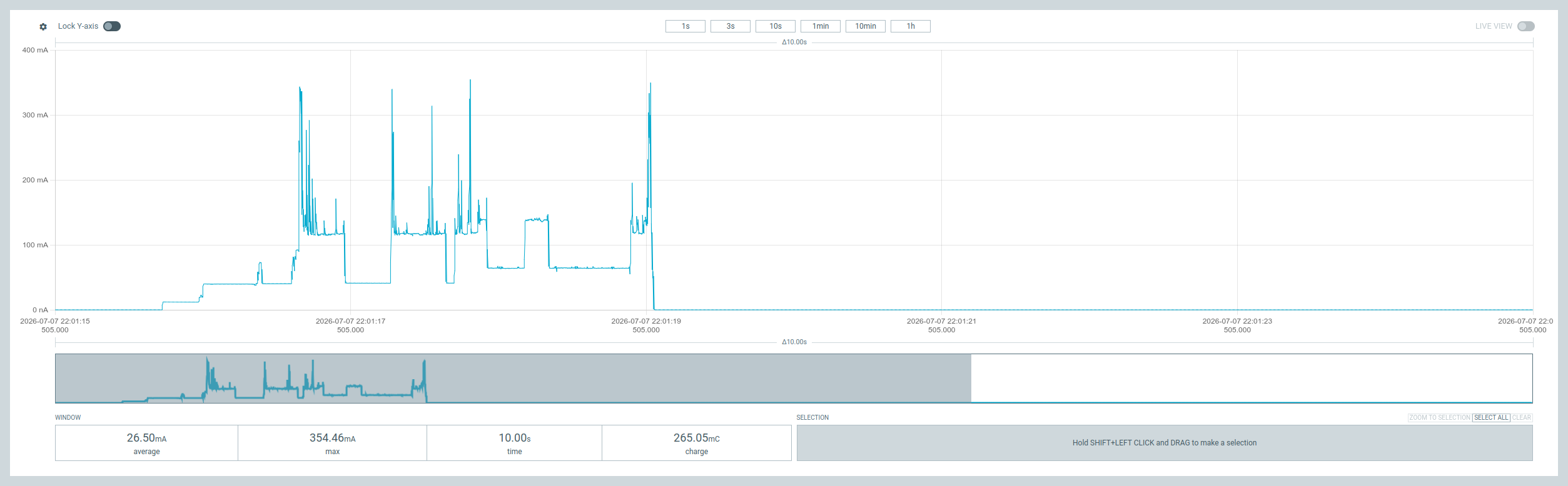
Zoom into that tail and change the axis from milliamps to microamps:
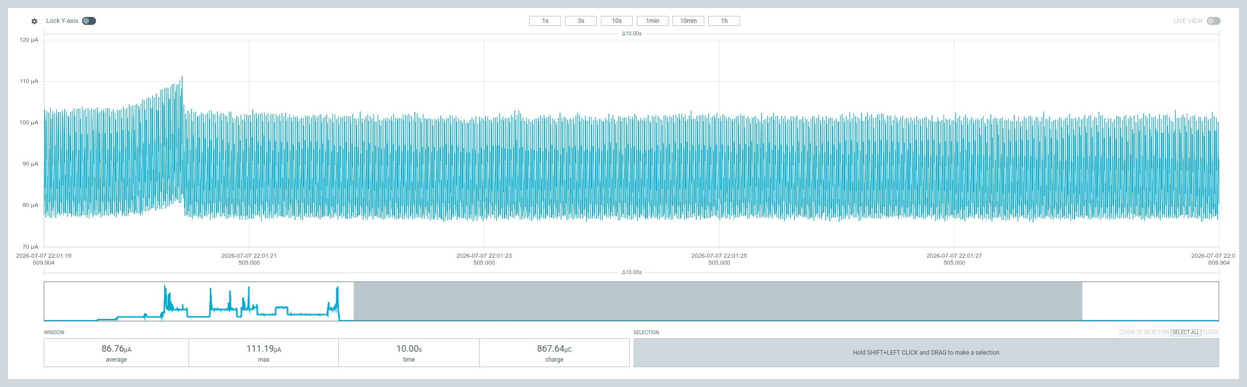
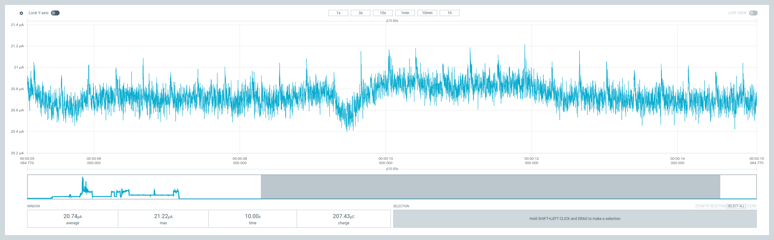
86.76 µA. The ESP32-WROOM-32E-N8 on this board should idle near 5-10 µA in deep sleep. So this is 8-17x too high, and unlike the WiFi burst it burns 24/7. This post is how it got to 20.74 µA, entirely in firmware. The two LDOs and the supervisor on this board are good parts doing their job; I never touched them. The fixes come down to three ideas every low-power ESP32 design has to get right: Hi-Z, pad latching, and RTC isolation.
If you want the board itself, it’s the compute board and its little HAL from earlier posts. The short version: an ESP32-WROOM-32E, a two-rail power design where a secondary rail (VCC_AUX) powers every peripheral and collapses in sleep, one GPIO to enable that rail, one for a config button, one for a status LED.
1. Hi-Z: what “off” actually means for a GPIO#
A GPIO is not a switch. It’s a pad with an output driver and two internal pull resistors, and current flows out of it in exactly two situations: you’re driving it into a load, or a pull resistor is enabled and the net has a DC path to the other rail. “High impedance,” or Hi-Z, is the state where the pad is an input with both pulls disabled: no driver, no pull, nowhere for current to go.
The status LED made this visible, literally. GPIO15 drives it, active-high, straight from the pad: GPIO15 -> LED -> resistor -> GND. Note what it is not connected to: VCC_AUX, the switched rail. Its only supply is the GPIO itself, which is the tell. The LED kept glowing in deep sleep even though the rail had collapsed, so the current had to be coming out of the pin.
The HAL’s first cut lumped GPIO15 in with the other strapping pins it “left alone” before sleep by calling gpio_reset_pin() on them. Read the ESP-IDF contract for that call carefully: select GPIO function, enable pull-up, disable input and output. It enables the pull-up. So GPIO15’s internal ~45 kΩ pull-up to 3.3 V now had a clean path through the LED to ground: tens of microamps, all sleep long. A dim LED is a current meter you can see across the room.
You can’t fix this one with Hi-Z. The LED is active-high; float its anode and the level is undefined. You fix it by driving GPIO15 low. GPIO15 is also the MTDO strapping pin, but low there only silences the ROM boot log on the next reset. It has nothing to do with flash voltage or boot mode, so it’s safe to hold low.
That single change, driving the LED pin instead of resetting it, took the floor from 86.76 µA to 48.67 µA. About 38 µA was a status LED nobody could see was on.
Every pin that isn’t driving something gets the other treatment: input, both pulls off, high-impedance. No driver, no pull, no path.
2. Pad latching: deep sleep forgets your pins#
Setting a pad correctly is only half of it, because deep sleep tears down the digital IO domain that holds that setting. Drive a pin low, call esp_deep_sleep_start(), and the pad can release as its domain powers off. The careful configuration you did evaporates at the exact moment it has to hold.
The fix is the pad hold. gpio_hold_en() freezes a pad in its current state; gpio_deep_sleep_hold_en() keeps those freezes latched through sleep. On the next boot you thaw them with gpio_deep_sleep_hold_dis() / gpio_hold_dis().
The rail-enable pin is why this is non-negotiable. VCC_AUX (the SD card, the I2C sensors, the whole peripheral rail) is switched by an LDO whose enable is GPIO13. To sleep clean you drive GPIO13 low. But if you don’t latch it, the pad releases in sleep, the enable line drifts back high, and the entire secondary rail powers back up under you. That is not hypothetical: it’s the exact bug I chased on my lora node. Reset the GPIO before sleep, forget the hold, and the rail sits at 3 V all night. So the HAL drives GPIO13 low, gpio_hold_ens it, then enables the deep-sleep hold. The config pin and the LED get the same drive-and-hold.
The pattern for any pin that must keep a level through sleep: set it, hold it, enable deep-sleep hold, release it on wake.
3. RTC pads: the sneaky 10 µA#
With the LED fixed and every unused header pin set to Hi-Z, the floor dropped from 48.67 µA to 31.08 µA, mostly a handful of header GPIOs (4, 14, 32, 33) that had simply been left floating. Better, still not right.
The last piece is that not all pads are equal. Most ESP32 GPIOs are digital-only: in deep sleep their domain powers down and they genuinely go quiet. But a subset, the RTC-capable pads, are also wired to the always-on RTC domain, and they retain their pull configuration in deep sleep. Tell an RTC pad “input, pull-up,” and it will hold that pull-up alive for the entire sleep. That is why plain Hi-Z wasn’t enough for pins 4/14/32/33: they’re RTC pads, so even after I disabled their pulls, a residual internal pull hung on and kept leaking.
The right tool is rtc_gpio_isolate(). For one RTC pad it disables input, output, pull-up and pull-down, then latches the pad: a true high-impedance island, with nothing left inside the chip to conduct. Espressif recommends exactly this call for GPIO12 on WROVER modules, for exactly this reason.
There’s one sharp catch. That RTC hold survives the wake reset, which is the whole point during sleep. But it means that if you isolate a pad and forget to release it on the next boot, the pad stays latched and every pinMode() / Wire.begin() / SPI.begin() on it silently does nothing. The peripheral is simply dead after the first sleep. So the HAL walks the RTC set and calls rtc_gpio_hold_dis() in begin() on every boot, before anything else touches those pins.
Isolating the RTC pads took the floor from 31.08 µA to 20.74 µA. That last ~10 µA was internal pull-ups, held alive on floating pads, invisible to everything but the meter.
How the HAL keeps this straight#
Applying three different rules across ~40 pins, correctly, on every single sleep, is exactly how you ship a bug like the glowing LED. So the HAL splits the decision from the action.
A pure, hardware-free core builds a sleep plan: a list of pins and what to do with each, either Hi-Z-and-hold or reset. It’s plain data with no ESP-IDF calls in sight, so it runs on a laptop under unit tests. A thin ESP32 driver then replays that plan against the real gpio_* / rtc_gpio_* functions. Whether a given Hi-Z pin gets rtc_gpio_isolate() or the plain digital Hi-Z path comes down to one predicate, isRtcGpio(), which is itself tested on the host.
What actually happens to each pin at sleep:
| Pins | At deep sleep |
|---|---|
Bus pins (I2C / SPI on VCC_AUX) | input + pulls off + gpio_hold_en |
| App-registered pins | same Hi-Z + hold |
| Any Hi-Z pin that is RTC-capable | rtc_gpio_isolate() instead, released on wake |
| Rail (13), config/MTDI (12), LED (15) | driven LOW + held |
| GPIO0 and input-only 34-39 | gpio_reset_pin() |
Two carve-outs are worth calling out, because they’re where the “just isolate everything” instinct bites:
GPIO0. On this board it has no external pull-up; it leans on the ESP32’s internal pull-up to strap boot-from-flash at every reset, including the deep-sleep wake. Isolate it and it floats, straight into download mode. So the plan refuses to Hi-Z or isolate GPIO0 even if the application asks for it. It stays reset, pull-up intact.
Input-only pins (34-39) have no output driver and no internal pull resistors. There is nothing to isolate and nothing to leak, so a plain reset is the correct and honest thing to do.
Using it#
From the application side this is small. Bring the board up, tell it which pins you drive, do your work, sleep:
#include <ComputeBoardHal.h>

static cbhal::ComputeBoardHal board;

void setup() {
    board.begin();                       // release last sleep's holds, bring up VCC_AUX

    // Pins this app drives -> forced to Hi-Z (and isolated, if RTC-capable) at sleep.
    board.registerPins({4, 14, 16, 17, 25, 26, 27, 32, 33});

    if (board.isConfigAsserted()) return;   // config button held: stay awake

    // ... read sensors / hit the network while VCC_AUX is up ...

    board.deepSleepSeconds(600);         // plan the pins, collapse the rail, sleep 10 min
}

void loop() {}
begin() and deepSleepSeconds() are the whole contract; registerPins() is how you extend the Hi-Z set beyond the on-board buses. The deep-sleep example wires this to a real duty cycle (join WiFi, one HTTPS GET, sleep) and takes its WiFi credentials at compile time so they never land in the binary by accident:
make upload-deep-sleep-example WIFI_SSID=MyNet WIFI_PASS=secret PORT=/dev/ttyUSB0
When you don’t want a pin floated#
registerPins() is opt-in, and that matters. A pin you never register is never forced to Hi-Z by the HAL. Outside the fixed on-board buses ({21, 22, 5, 18, 19, 23}) and the strapping set, the HAL leaves your pins alone. So if a pin has to hold a level through sleep, say it gates an external load that must stay off or holds a chip in reset, you leave it unregistered and drive-and-latch it yourself, exactly like the HAL does for the rail:
// GPIO25 must stay LOW through sleep, not float. Don't register it; drive + latch it.
pinMode(25, OUTPUT);
digitalWrite(25, LOW);
gpio_hold_en(GPIO_NUM_25);      // deepSleep()'s deep-sleep hold keeps it latched
board.deepSleepSeconds(600);   // begin() releases the hold on the next boot
Two things the HAL will not let you do, on purpose: register GPIO0 (it must keep its pull-up for the boot strap, so the plan drops it), and hold a level on an input-only pin (34-39 have no output driver). Everything else is yours to place.
Where the floor is, and why the LDOs stay#
20.74 µA is the module’s own deep-sleep current (~5 µA) plus the quiescent draw of the always-on parts: the LDO that feeds the ESP32 and the voltage supervisor watching the rail. That is not leakage. That’s the datasheet. The XC6220 and the TPS3839 are doing exactly their jobs, and the XC6220’s headroom is what survives the ~350 mA WiFi bursts without browning out. Trading that away to shave a few microamps of quiescent would be optimizing the wrong thing. Firmware’s job was to stop wasting current, and it did: 86.76 µA down to 20.74 µA, a 4x cut, with zero board changes.
The rules generalize to any ESP32 low-power design:
- Put every pin in a defined state before sleep. Unused pins go Hi-Z with pulls off; a pin that needs a level gets driven.
- Latch anything that must survive sleep, and release it on wake.
- RTC-capable pads get isolated, not merely floated, and un-isolated on the next boot, or your peripherals die after the first cycle.
- Know your strapping pins. Hold one wrong and you get a boot loop; leave one floating and you get a leak.
The HAL, the unit tests, and a longer pin-by-pin writeup (including the full when-to and when-not-to for rtc_gpio_isolate()) are in the compute-board-hal repo.